Introduction
Architectural drawings
Introduction
While studying mathematics
it can often happen that although the calculations have been made, we have not
thought about how we can use the aquired information in real life. One of such
fields where we don’t think it relates to our daily life and work is calculating
geometrical bodies (area, volume , angles ).
In practice , however, it
is of great importance . For example in piece work we must be able to calculate
our wage (surfaces, volumes ). Also when ordering materials we must be able to
calculate the volume of different objects ( rectangulars , triangles , pyramids
, cylinders , etc .).
In order to plan ahead it
is necessary to have the architectural drawings . If you ask the question why
does a builder need drawings, it might have different answers.
But one of the main
reasons is for the builder to get an idea of the planned building
. Namely , if you start building , it is possible to install an object in
nature on the basis of the drawing; through pre- design we obtain a
thoughtfully planned and meaningful result that has a predetermined shape and
size.
When using professional
construction workers to build a structure, the contractor can clearly convey
their wishes and vison of the planned structure through the project drawings.
All these activities will take place in everyday life through
simple mathematical operations . Therefor this study material is designed to
complement Your math studies through practical examples.
Standards
Since
nowadays many large collaborative projects and buildings become international
objects, it is increasingly more important that the drawings can be understood
by all the involved partners the same way, since a project drawing can include
a lot of symbols and meanings that are not universally agreed upon.
In the
interest of clarity, the international standard (ISO – the
International Organization for Standardization) has been created but next to them local national
standards apply that regulate the cooperation between builders and contractors
in a country. There is also European Standards ( EN) and standards
of the Republic of Estonia ( EVS - Estonian Centre for Standardization ). The
aim of the standards is for all the involved partners to understand the laws,
rules and symbols used in the process of construction or production in the same
way.
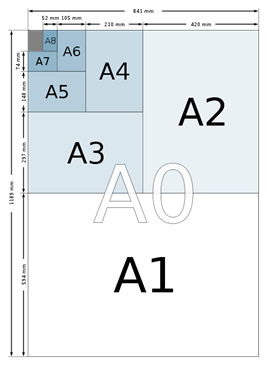
For paper sizes one of the best-known standards
is ISO 216. This standard defines 3
paper sizes “A” , “B” and “C”. Series “C” is used for envelopes. The
standardized paper sizes were first introduced in 1922 in Germany and are called
DIN 476 in Germany. This evolved into the international metric system that provides a universal
understanding of the sizes and measurements used in a drawing. As can be seen
in the figure below the letters A , B , or C with a number behind them, are
used to characterize the size of the paper format.
Paper in
the „A“ series format has a 1:√2 aspect ratio. It is known that √2 is an
irrational number (when rounded equals 1: 1.4142 ) . The result is rounded to the nearest millimetre. The
most frequently used of this series is the size A4 which is 210 mm × 297 mm
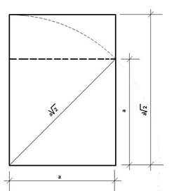
As we all know, ![]() is used to calculate the diagonal of a square. The same
principle is used to calculate the width and length of the “A” series paper
format.
is used to calculate the diagonal of a square. The same
principle is used to calculate the width and length of the “A” series paper
format.
For example, if we take the A4 format
, where a = 210 mm then ![]() = 296 , 98
≈ 297 mm
= 296 , 98
≈ 297 mm
The English language world uses its approximate the " Letter "
format, with the dimensions 216 x 279.
(which we might come across while printing on a computer)
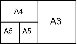
The number behind the letter represents an exact size also known as the
format. The smallest possible number is 0, but contrarily it is the biggest
possible format with the measurements 841 x 1189 mm. A0 is defined so that it has an area of 1 square metre, prior to rounding.
Successive
paper sizes in the series (A1, A2, A3, etc.) are defined by halving the
preceding paper size.
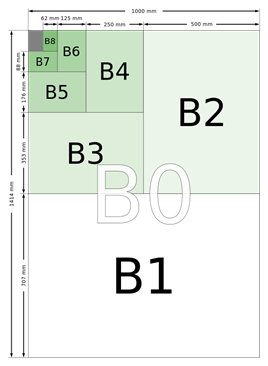
The B
series is defined as a subsidiary series of sizes obtained by placing the geometrical
means between adjacent sizes of the A series in sequence. To get the size of B1
the geometric mean of A1 and A0 is taken.
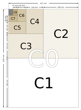
The C
series formats are geometric means between the B series and A series formats
with the same number (e.g., C2 is the geometric mean between B2 and A2). For
example, if an A4 page is folded in half so that it is A5 in size, it will fit
into a C5 envelope (which will be the same size as a C4 envelope folded in
half).
|
|
A- |
B- |
C- |
|
0 |
841 × 1189 |
1000 × 1414 |
917 × 1297 |
|
-1 |
594 × 841 |
707 × 1000 |
648 × 917 |
|
-2 |
420 × 594 |
500 × 707 |
458 × 648 |
|
-3 |
297 × 420 |
353 × 500 |
324 × 458 |
|
-4 |
210 × 297 |
250 × 353 |
229 × 324 |
|
-5 |
148 × 210 |
176 × 250 |
162 × 229 |
|
-6 |
105 × 148 |
125 × 176 |
114 × 162 |
|
-7 |
74 × 105 |
88 × 125 |
81 × 114 |
|
-8 |
52 × 74 |
62 × 88 |
57 × 81 |
|
-9 |
37 × 52 |
44 × 62 |
40 × 57 |
|
-10 |
26 × 37 |
31 × 44 |
28 × 40 |
Source: Standard ISO 216
Lets bring an example
of calculating the geometricl mean. First, we look at the formula
The formula is: 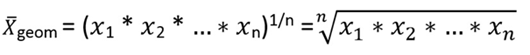
We derive the measurements
of B1 through A0 and A1
For example, the geometric mean for the side lengths
841 mm and 594 mm is:
![]() = 706.79 mm ≈ 707 mm
= 706.79 mm ≈ 707 mm
And for the side lengths 1189 mm and 841 mm:
![]() = 999.97 mm ≈ 1000 mm
= 999.97 mm ≈ 1000 mm
Therefore, derived measurements of B1 are 707 x
1000 mm
Geometric mean is usually related
to sequences. In this example, both format sizes were proportionally changed .
This calculation can also be used to
calculate the compromise variant of movie and TV screen size ratios
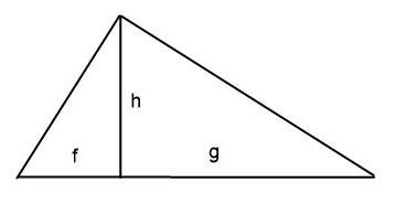
The portrayal of the geometric mean
is also similar to the triangle height formula and would look like this:
![]()
In the drawings letter standards are
also used.
In everyday life, however, we use
thousands of standards that are industry specific, such as standards for
mechanical engineering, the chemical industry etc .
International System of Units
Before the metric system (of measurement) was
introduced internationally, each country was using a different measuring unit
that caused a lot of confusion. Today, most countries have adopted a uniform
international system which has made communication and bureaucratic procedures a
lot easier.
Unified quality standards
Another example is a situation
where we have a different understanding of the quality of a finished product,
detail or building on the local level . Hence, in order to have the same
understanding for all the parties involved, our activities must be based on
quality standards or laws.
Drawings
When familiarizing yourself with the drawings you
first must clarify all the symbols used.
In some drawings and plans (topographical symbols ) symbols are explained .
However, in order to have a better understanding of the drawing, it is useful
to know them in advance.
Different standards are used in construction and
mechanical engineering drawings. Their difference lies in the types of lines,
dimensions and symbols used.
Since constructors must sometimes use drawings for mechanical engineering, it
is useful for them to know the notations and definitions of both standards
Construction
Projects
To define a construction project - it is a set of necessary documents ,
which consists of a letter of explanation, technical drawings , technical
safety instructions, operational and maintenance manuals and other relevant
documents .
Scale
If we look on the mathematical side of
constructional design, scale plays an important role.
Plans are usually "scale drawings", meaning that the plans are drawn
at specific ratio relative to the actual size of the place or object. Various
scales may be used for different drawings in a set.
The scale can be used to either increase or
decrease the real situation. For example, buildings and constructions are
usually so large that in order to portray them on a drawing we must
reduce their measurements and dimensions proportionally.
The opposite situation arises with small details. For
example, to sketch a small screw or a shim it is reasonable to increase its
size on paper to be able to add remarks or measurements on the drawing.
The
length of a line on a drawing or a maps is usually expressed as a fixed value.
The length of the drawn line is chosen to represent a fixed relationship of the
length of the real objekt. Either the number scale, explanatory scale or
topographic linear scale can be used.
In the construction industry, plan and map scale is
used. Corresponding measurement on a project drawing is called plan scale.
Geographical measurements are portrayed as a map scale
Map scale is a ratio which compares a measurement
on a map to the actual distance between locations identified on the map. This
can be used to mark building sizes on a map.
A scale of 1 : 100 means that the real distance is
100 times the length of 1 unit on the map or drawing. (metric scale)
An scale of 1:50 means that 1cm corresponds to 50
cm or 0,5 m.
A
map scaled to 1 : 100 000 means that the real distance is 100 000 times the
length of 1 unit on the map or drawing. At this scale, 1cm on the map represents 1km on the ground and 5cm
represents 5km.
This
result was achieved using the following calculation: 1 km = 100 cm x 1000 cm =
100 000 cm
Types of scales
Number scale
This scale can be used to
calculate lengths on a map or the ground
For
example expressed as a ratio like 1 : 500. This simply means that 1 unit on the map represents 500 units on the
ground.
![]()
Linear scale (bar scale)
A person using the map can use a
pair of dividers to measure a distance by comparing it to the linear scale. The
length of the line on the linear scale is equal to the distance represented on
the earth multiplied by the map or chart's scale.
“Transversal” scale
A pair of divders is also needes when using a
transversal scale. An additional option here is to use the hight of the scale,
meaning we can divide the basic units into smaller units – tenths and
hundreds.
Accuracy of a scale
The smallest length shown on maps or plans is 0,2 mm
Excercises
Convert the scale
a. 1
: 10 000
b. 1
cm – 20 km
c. 1
: 500
d. 1
cm – 600 m
e. 1
: 1000
Practice test
(link)
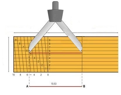
Measuring in inches (imperial system)
Even though we use the SI-system or so
called metric system, in some construction areas the imperial system is used.
On area it is used in quite often is carpentry. It is used for wooden materials
and also for pupes. Their measurments are usually given in inches.
Threfor we’ll look a bit more into the imperial
system
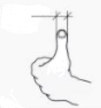
In the old days when the International
measuring standards had not been developed yet, people used their body parts
for measuring. As you can imagine, the size of a body part can be very different
for different people - this caused a lot
of confusion.
For excample the norweigan-danish inch
equaled 26,2 mm but the swedish one 24,7 mm . Also the american and britis
measurments differ.
Nowadays the measurments are set fest
in the following way:
1 inch (1”) = 25,4 mm
1 foot (1’) = 12
inches (12“) = 304,8 mm
1 ell = 21 inches
(21”) = 533 mm
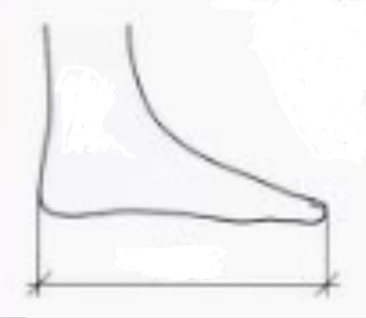
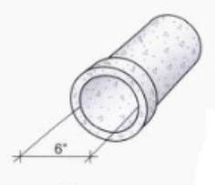
Samples of pipe measurements:
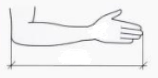
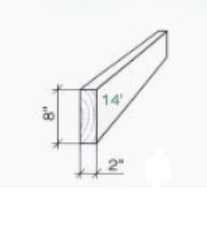
A wooden plank:
Diffences
between the metric and imperiaal system
The international standard symbol for
inch is in but traditionally the inch is denoted by a double prime,
which is often approximated by double quotes. Subdivisions of an inch are
typically written using dyadic fractions with odd number numerators.
In metric system we use the radix point
to separate the integer part of a number
from its fractional part. For example 0,1; 0,01; 0,001 etc.
For example:
If 1 inch (1’’)=25,4 mm then:
![]() inches =
inches = ![]()
![]() inches =
inches = ![]()
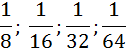
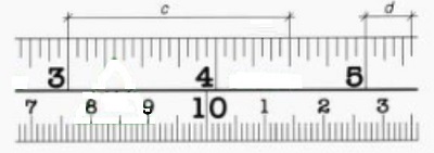
Calculating with fractions
For a better understanding of the
differences between the two system, lets look at the measuring tape. The
measuring tape shows both systems inches and cm.
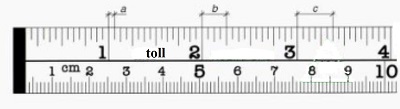
As mentioned before, the main
difference is that the imperial system uses simple fractions to denote the
subdivisions of an inch. On the portrayd measuring tape, the smallest fraction
is 1/16 of an inch.
The different segments are measured as:


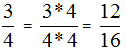
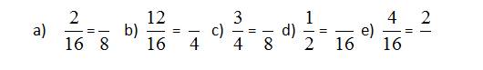
To expand the simple fraction, we
multiply the numerator and denominator with a number
For example
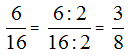
To reduce (or simplify) a single
fraction, divide the numerator and denominator by their Greatest Common Factor
(GCF)
For example
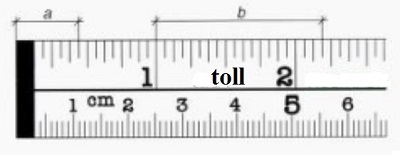
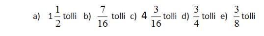
The next drawing:


On this drawing:
![]()
![]()
For
example:
Converting feet to inches
1 foot equals 12 inches, then 2´=24´´
![]() gives 24´´+6´´=30´´
gives 24´´+6´´=30´´
With larger values we convert as
follows:
a)
Given ![]() we can write it as
we can write it as ![]()
b) Now we convert feet to inches: ![]()
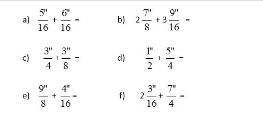
Exercice
1. Reduce
or expand the fractures and fill out the empty spaces
2. Convert
into mm
3. Give
the solution in metric system
4. Convert
(feet and inches)